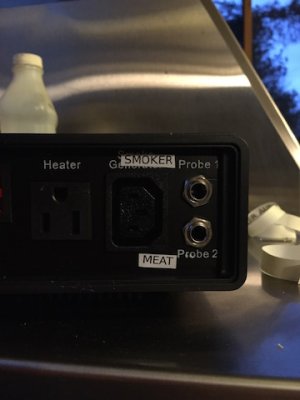
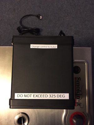
I installed the permanent probe and the controller bypass this past weekend. I included my process and some photos on the probe installation under the appropriate category "How to install a permanent Auber temperature probe". Below is information on bypassing the controller.
I chose to install a switch so that I could go back to the stock analog controller should I have an issue with the Auber or one of its probes.
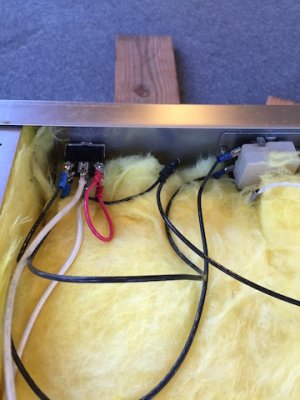
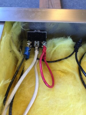
First, I purchased a common DPDT panel mount 2-position toggle switch with screw terminals, rated for 15A, from Amazon. Below is the link to the switch that I bought. I like the screw terminals because it allowed me to use crimp-on terminals on the various wires so that I could easily remove them later if needed. Also, as you can see in the photo below, I found that by removing the screws in the center terminals, the spade terminal that came on the smoker would slip on the switch terminal without having to re-terminate it. Be sure and check the switch terminals (I did this with a common volt-ohm meter) before installing the wiring to make sure which terminals are "closed" and which are "open" when the switch is thrown in each position. On the switch I bought, I found that when the switch was thrown in one direction, the terminals on the opposite end of the switch were the ones that were actually "closed". (As you can see from the wiring diagram below, the terminals in the center of the switch connect to the heating element of the smoker. When the switch is thrown one way, the heating element is connected to the stock SI controller. When the switch is thrown the other way, the heating element is connected to the jumper and is controlled by the Auber.)
http://smile.amazon.com/gp/product/B00K858QG2/ref=oh_aui_detailpage_o04_s00?ie=UTF8&psc=1
Like others have posted, I decided to mount the switch in the top of the smoker near the right rear corner at the right edge of the label. I like the location now (sorry I didn't take a picture), but drilling in that location was a bear. The sheet metal and label together are every bit of 1/8" thick or more. The diameter of the switch is 1/2", so I drilled a small pilot hole, then a little larger hole and then finally the 1/2" hole. Let the drill turn slowly and be patient because the stainless is very hard. I used cutting oil to help cool the bits. Regular motor oil will work almost as well.
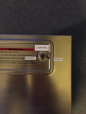
I made up all of the jumpers and terminated all of the wiring before installing the switch so that it would be easier to access the terminal screws on the switch. Make sure that you use 14 AWG wire or larger for all conductors. I used stranded wire since it is easier to work with. I found that I had to lengthen the wire that goes to the power indicator light due to my switch location (this wire does not need to be 14 AWG). I then installed the switch with the threaded lock nut provided (see photo). I installed my switch so that when thrown to the left (looking at the top of the smoker from the front) the standard SI controller was connected and when thrown to the right, the Auber was in control. I have made up some labels and once I have installed them, I will take a photo and update this post.
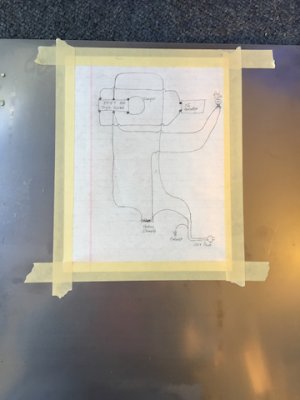
I drew up a crude wiring diagram and taped it to the inside of the back panel of the smoker (see photo) so that it would be handy should I have to work on something in the middle of a smoke (which I did on my first smoke, as detailed below).
Before re-installing the back of the smoker, I tested it with and without the Auber to make sure that my wiring was correct.
During my first smoke, I found that the heating element would turn off about 45 minutes into the smoke. After much stress, I found that I could wiggle the power cord and the element would come back on (as evidenced by the light on the top of the smoker). About 45 minutes later, the element would stop working again. Each time this happened, I could wiggle the cord and get it to come back on. Finally, I decided to take the back off the smoker and troubleshoot the problem. As it turned out, the crimp-on connector on the heating element conductor that connects to a spade connector on the power cord (the one that comes from the factory encased in shrink tube) was loose. I cut off the shrink tube from both power conductors and re-terminated all of the conductors with new crimp-on connectors and wrapped well with electrical tape. The rest of the smoke was flawless.
The moral of the story is that if you are doing the mod above and have the back of the smoker off, go ahead and cut off that factory installed shrink tube and re-terminate the conductors and then reinstall more shrink tube. It may save you some headaches down the road.
P.S. - You can buy a fairly inexpensive terminal crimp kit from Lowes or other stores that comes with a selection of crimp-on terminals and the stripper/crimper. This is a handy thing to have around the house because a lot of appliances, etc. use them. Below is a link to one that I found on Amazon.
http://www.amazon.com/Neiko-50413A-Solderless-Connection-Stripping/dp/B000K7GRCI/ref=sr_1_1?s=hi&ie=UTF8&qid=1419354945&sr=1-1&keywords=terminal+crimp+kit


